Monday, December 16, 2013

Code worked

                                                        Code Worked!!!!!!!!!!!!

To Be Continue

First and foremost, I would like thank the team that made all of this possible. Jeff Francois and Jeff Hutchinson, thank you for your participation on this project. Jeff F. did a terrific job with the coding, I'm truly please with the final outcome. Jeff H. did a great job with the write up, you summed up everything the team went through to make this project come to life. Great work gentleman...
This concludes our project...

 "TO BE CONTINUE!!!!"

Your Host: Tito J. Arana

December 13 - Hard Work Pays Off Cont.

Roboplow Mini Part 2:

Saturday, December 14, 2013

December 13 - Hard Work Pays Off

We present to you Roboplow....

December 13 - Roboplow Mini

Ladies and Gentlemen (drum roll!!!!!!)..... Roboplow Mini, brought to you by the Department of Mechanical Engineering:

Thursday, December 12, 2013

December 12 - Code Used To Run Roboplow

This is our final code we are using to run Roboplow. Our Robot is alive!!!!!! A final video soon to come.
// Use this code to test your Obstacle Avoiding vehicle with the Arduino board:
// this constant won't change. It's the pin number
// of the sensor's output:
const int pingPin = 7;
// Motors
int motor_left[] = {6,8};
int motor_right[] = {3,5};
int ledPin = 13; // LED connected to digital pin 13
// Setup
void setup() {
Serial.begin(9600);
// Setup motors
int i;
for(i = 0; i < 3; i++){
pinMode(motor_left[i], OUTPUT);
pinMode(motor_right[i], OUTPUT);
pinMode(ledPin, OUTPUT);
}
digitalWrite(motor_left[2], HIGH);
digitalWrite(motor_right[2], HIGH);
}
// Loop
void loop() {
long duration, inches, cm;
// The PING))) is triggered by a HIGH pulse of 2 or more microseconds.
// Give a short LOW pulse beforehand to ensure a clean HIGH pulse:
pinMode(pingPin, OUTPUT);
digitalWrite(pingPin, LOW);
delayMicroseconds(2);
digitalWrite(pingPin, HIGH);
delayMicroseconds(5);
digitalWrite(pingPin, LOW);
// The same pin is used to read the signal from the PING))): a HIGH
// pulse whose duration is the time (in microseconds) from the sending
// of the ping to the reception of its echo off of an object.
pinMode(pingPin, INPUT);
duration = pulseIn(pingPin, HIGH);
// convert the time into a distance
inches = microsecondsToInches(duration);
cm = microsecondsToCentimeters(duration);
Serial.print(duration); Serial.println();
Serial.print(inches); Serial.print("in, ");
Serial.print(cm); Serial.print("cm");
Serial.println();
if (cm>170)
{
Serial.println("Moving Forward");
drive_straight();
drive_forward();
delay(500);
}
{
if (cm<100)
{
Serial.println("Obstacle Very Close");
Serial.println("Evasive Manuever");
drive_straight();
drive_backward();
delay(1000);
}
if (cm<=170&&cm>100)
{
motor_stop();
Serial.println("Turning Left");
turn_left();
Serial.println("Reverse");
drive_backward();
delay(3000);
Serial.println("Turning Right");
turn_right();
Serial.println("Moving Forward");
drive_forward();
delay(1000);
drive_straight();
drive_forward();
delay(1000);
}
}
motor_active();
motor_inactive();
delay(1);
}
// Drive
void motor_active(){
digitalWrite(ledPin, HIGH); // set the LED on
delay(500); // wait for a second
}
void motor_inactive(){
digitalWrite(ledPin, LOW); // set the LED off
delay(500); // wait for a second
}
void motor_stop(){
digitalWrite(motor_left[0], LOW);
digitalWrite(motor_left[1], LOW);
delay(25);
}
void drive_straight(){
digitalWrite(motor_right[0], LOW);
digitalWrite(motor_right[1], LOW);
}
void drive_forward(){
analogWrite(motor_left[0],200);
digitalWrite(motor_left[1], LOW);
}
void drive_backward(){
digitalWrite(motor_left[0], LOW);
digitalWrite(motor_left[1], HIGH);
}
void turn_left(){
digitalWrite(motor_right[0], HIGH);
digitalWrite(motor_right[1], LOW);
}
void turn_right(){
digitalWrite(motor_right[0], LOW);
digitalWrite(motor_right[1], HIGH);
}
long microsecondsToInches(long microseconds)
{
// there are
// 73.746 microseconds per inch (i.e. sound travels at 1130 feet per
// second). This gives the distance travelled by the ping, outbound
// and return, so we divide by 2 to get the distance of the obstacle.
return microseconds / 148;
}
long microsecondsToCentimeters(long microseconds)
{
// The speed of sound is 340 m/s or 29 microseconds per centimeter.
// The ping travels out and back, so to find the distance of the
// object we take half of the distance travelled.
return microseconds / 58;
}
view raw Roboplow Code hosted with ❤ by GitHub

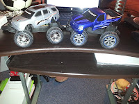
December 11 - This Is It

 At only two days away I had no choice but to go back to Walmart and purchase another RC car. This time I did not throw away the box or took the RC apart but what I did (and this I should of done with the first RC I bought) to put batteries on the RC and the control and make sure that the forward and back worked. Luckily this one seem to work flawlessly. Once I tested that all terminals were fine, I started soldering everything back with caution. I didn't want to alter anything with the new RC car. So far is looking great according to plan. Each terminal that's being solder is working great. Now to put it back together and move forward with Roboplow. Ladies and Gentlemen, we are back in business. Two RC car later:


December 10 - Once Again

Today I rush to buy a new RC car at a local Walmart and begin all the soldering once again. At this point we are pressure for time. Little did we know that something major like this would show up. But then again with any problem there's a solution. Once again I took all the unnecessary parts off the RC and left what is important to us. First I solder a cable to ground and another cable to positive just so I can run a code test the turns and also the motor forward and back. Now that I have ground solder to a cable and so is positive, I plug the leads to the breadboard along with the proper wiring and fail. Now the forward and right turn don't work on the brand new RC car. My theory is that these RC car have some sort of defect. At this point I had taken the RC car apart and thrown the box away to return the car.

December 9 - No!!!!!!!

Almost at the end of the finish line and here's an obstacle. Testing the code, the ping sensor, the new body style and battery, Roboplow seems to not want to turn left or right even though the serial monitor is reading left and right. It just doesn't make sense. We checked, double checked and triple checked line by line. Why all of the sudden Roboplow doesn't want to make any turns? Our next point is to check all of the wires and bingo!!!! We figured out that terminals left and right do not work. Our theories:

1. When soldering the terminal left and terminal right three times (yes three time it came undone) we must of alter something with the chip

2. Maybe we did bad wiring and burnt the chip

3. Manufacture default

At this point we all got discourage, but like I told me team "This is part of our challenge gentlemen, we now have to come up with a solution." At this point my solution (quickest solution being that we only had three days left) was to purchase a new RC toy car.

December 5 - Body Part Updated

Ladies and gentlemen, here is our new body style for Roboplow. Free access to the Arduino USB port, access to the RC's motherboard, opening in the sides for LED, opening for an On/Off switch at the top and the Arduino board holder:


December 4 - Back To The Code

While the body was getting printed one more time with all the updates done on the 3rd. Jeff F and I came up with the idea of adding LED to Roboplow. We wired some LED to the breadboard added a couple more lines of arguments to our code and we came up with this:

December 3 - Body Update

After the body was printed, I came up with a few more ideas to add. I wanted to implement a few things, like make an opening for a free access to the Arduino port, add an extruded part to hold in place the Arduino, make a special box for the battery holder, make an opening in the middle of base for free access to the RC's motherboard. Here's the Solidwork part:


December 3 - Putting All The Pieces Together

We now have a working sensor, the ping sensor is able to see an obstacle and figure out to go on reverse and keep moving forward in a different direction. We are very close to our final assemble, today I got the body. It was pretty exciting to put everything together, the Arduino, the breadboard, the battery, the Ping Sensor and this is what it looks like all together:


December 2 - Ping Sensor Trials

While the body is getting printed, we go back to work on the code. So far we have the Ping Sensor to see an object in front of it, stop and go in reverse. This is what is looks like:

Monday, December 9, 2013

November 28 - Body Work

Now that we have our code to work, it is time to work on the body style. As a group we threw different ideas as to what the body should look like. Both Jeff F. and Jeff H. wanted to make a body style of a pick up truck. Really good idea but Roboplow need to looked more futuristic. At one point we all agreed to make a simple box, but then we figured that was too simple. Until on a Thanksgiving aftenoon, I came up with this idea:

November 27 - Third Attempt

Second code failed. This code did make the ping sensor to work (awesome!!) but the only thing that worked was the ping sensor. The RC motors didn't want to turn on (not good), we have a working sensor but not a working car. Again we change the language to make it our own but unfortunately the RC did not want to budge. All until we came across this code (they do say the third one is the charm):
// Use this code to test your Obstacle Avoiding vehicle with the Arduino board:
// this constant won't change. It's the pin number
// of the sensor's output:
const int pingPin = 7;
// Motors
int motor_left[] = {6,8};
int motor_right[] = {3,5};
int ledPin = 13; // LED connected to digital pin 13
// Setup
void setup() {
Serial.begin(9600);
// Setup motors
int i;
for(i = 0; i < 3; i++){
pinMode(motor_left[i], OUTPUT);
pinMode(motor_right[i], OUTPUT);
pinMode(ledPin, OUTPUT);
}
digitalWrite(motor_left[2], HIGH);
digitalWrite(motor_right[2], HIGH);
}
// Loop
void loop() {
long duration, inches, cm;
// The PING))) is triggered by a HIGH pulse of 2 or more microseconds.
// Give a short LOW pulse beforehand to ensure a clean HIGH pulse:
pinMode(pingPin, OUTPUT);
digitalWrite(pingPin, LOW);
delayMicroseconds(2);
digitalWrite(pingPin, HIGH);
delayMicroseconds(5);
digitalWrite(pingPin, LOW);
// The same pin is used to read the signal from the PING))): a HIGH
// pulse whose duration is the time (in microseconds) from the sending
// of the ping to the reception of its echo off of an object.
pinMode(pingPin, INPUT);
duration = pulseIn(pingPin, HIGH);
// convert the time into a distance
inches = microsecondsToInches(duration);
cm = microsecondsToCentimeters(duration);
Serial.print(duration); Serial.println();
Serial.print(inches); Serial.print("in, ");
Serial.print(cm); Serial.print("cm");
Serial.println();
if (cm>10)
{
Serial.println("Moving Forward");
drive_forward();
delay(1000);
}
else
{
if (cm<10)
{
Serial.println("Obstacle Very Close");
Serial.println("Evasive Manuever");
motor_stop();
drive_backward();
delay(200);
}
else
{
motor_stop();
Serial.println("Turning Left");
turn_left();
Serial.println("Reverse");
drive_backward();
delay(800);
Serial.println("Turning Right");
turn_right();
Serial.println("Moving Forward");
drive_forward();
delay(500);
drive_straight();
drive_forward();
delay(1000);
}
}
motor_active();
motor_inactive();
delay(1);
}
// Drive
void motor_active(){
digitalWrite(ledPin, HIGH); // set the LED on
delay(500); // wait for a second
}
void motor_inactive(){
digitalWrite(ledPin, LOW); // set the LED off
delay(500); // wait for a second
}
void motor_stop(){
digitalWrite(motor_left[0], LOW);
digitalWrite(motor_left[1], LOW);
delay(25);
}
void drive_straight(){
digitalWrite(motor_right[0], LOW);
digitalWrite(motor_right[1], LOW);
}
void drive_forward(){
digitalWrite(motor_left[0], HIGH);
digitalWrite(motor_left[1], LOW);
}
void drive_backward(){
digitalWrite(motor_left[0], LOW);
digitalWrite(motor_left[1], HIGH);
}
void turn_left(){
digitalWrite(motor_right[0], HIGH);
digitalWrite(motor_right[1], LOW);
}
void turn_right(){
digitalWrite(motor_right[0], LOW);
digitalWrite(motor_right[1], HIGH);
}
long microsecondsToInches(long microseconds)
{
// there are
// 73.746 microseconds per inch (i.e. sound travels at 1130 feet per
// second). This gives the distance travelled by the ping, outbound
// and return, so we divide by 2 to get the distance of the obstacle.
return microseconds / 148;
}
long microsecondsToCentimeters(long microseconds)
{
// The speed of sound is 340 m/s or 29 microseconds per centimeter.
// The ping travels out and back, so to find the distance of the
// object we take half of the distance travelled.
return microseconds / 58;
}
view raw Final Attempt hosted with ❤ by GitHub
This code works!!!! Our ping sensor was picking up obstacles and also was making the RC move forward when no obstacles were present and going in reverse when there was an obstacle. This code also made the wheels turn. We changed a lot of line to make it our own.

November 27 - Second Attempt

First code failed. The ping sensor did not picked up any obstacles, in fact the ping sensor did not turn on. We tried different things to make this code to work. We changed the language to make it our own but the ping sensor did not turn on. We then went back to the website we got the code from and later we found out the creators of this code were using a different sensor similar to ours. We then came across this:
const int numOfReadings = 10; // number of readings to take/ items in the array
int readings[numOfReadings]; // stores the distance readings in an array
int arrayIndex = 0; // arrayIndex of the current item in the array
int total = 0; // stores the cumlative total
int averageDistance = 0; // stores the average value
// setup pins and variables for SRF05 sonar device
int echoPin = 7; // SRF05 echo pin (digital 2)
//int initPin = 13; // SRF05 trigger pin (digital 3)
unsigned long pulseTime = 0; // stores the pulse in Micro Seconds
unsigned long distance = 0; // variable for storing the distance (cm)
int motor1Pin1 = 3; // forward
int motor1Pin2 = 4; // reverse
//int enable1Pin = 9; //
int motor2Pin1 = 5; // Steer right
int motor2Pin2 = 6; // Steer left
//int enable2Pin = 10; //
void setup() {
// set the motor pins as outputs:
pinMode(motor1Pin1, OUTPUT);
pinMode(motor1Pin2, OUTPUT);
//pinMode(enable1Pin, OUTPUT);
pinMode(motor2Pin1, OUTPUT);
pinMode(motor2Pin2, OUTPUT);
//pinMode(enable2Pin, OUTPUT);
// set enablePins high so that motor can turn on:
//digitalWrite(enable1Pin, HIGH);
//digitalWrite(enable2Pin, HIGH);
pinMode(echoPin, OUTPUT); // set init pin 3 as output
pinMode(echoPin, INPUT); // set echo pin 2 as input
// create array loop to iterate over every item in the array
for (int thisReading = 0; thisReading < numOfReadings; thisReading++) {
readings[thisReading] = 0;
}
}
void loop() {
digitalWrite(echoPin, HIGH); // send 10 microsecond pulse
delayMicroseconds(10); // wait 10 microseconds before turning off
digitalWrite(echoPin, LOW); // stop sending the pulse
pulseTime = pulseIn(echoPin, HIGH); // Look for a return pulse, it should be high as the pulse goes low-high-low
distance = pulseTime/58; // Distance = pulse time / 58 to convert to cm.
total= total - readings[arrayIndex]; // subtract the last distance
readings[arrayIndex] = distance; // add distance reading to array
total= total + readings[arrayIndex]; // add the reading to the total
arrayIndex = arrayIndex + 1; // go to the next item in the array
// At the end of the array (10 items) then start again
if (arrayIndex >= numOfReadings) {
arrayIndex = 0;
}
averageDistance = total / numOfReadings; // calculate the average distance
delay(10);
// check the average distance and move accordingly
if (averageDistance <= 10){
// go backwards
digitalWrite(motor1Pin1, LOW);
digitalWrite(motor1Pin2, HIGH);
digitalWrite(motor2Pin1, HIGH);
digitalWrite(motor2Pin2, LOW);
}
if (averageDistance <= 25 && averageDistance > 10) {
// turn right
digitalWrite(motor1Pin1, HIGH);
digitalWrite(motor1Pin2, LOW);
digitalWrite(motor2Pin1, HIGH);
digitalWrite(motor2Pin2, LOW);
}
if (averageDistance > 25) {
// go forward
digitalWrite(motor1Pin1, HIGH);
digitalWrite(motor1Pin2, LOW);
digitalWrite(motor2Pin1, LOW);
digitalWrite(motor2Pin2, LOW);
}
}
view raw Second Attemp hosted with ❤ by GitHub

November 27 - First Attempt

Our first attempt to make the ping sensor pick up obstacles and stops at midway, turn either left or right then continue moving forward. When we looked online for similar codes. We came across this, we figured it would work:
#include <Servo.h>
//Declare Servos
Servo leftservo; //Left wheel servo
Servo rightservo; //Right wheel servo
Servo scanservo; //Ping Sensor Servo
const int turntime = 500; //Number of milliseconds to turn when turning
const int pingPin = 7; //Pin that the Ping sensor is attached to.
const int leftservopin = 9; //Pin number for left servo
const int rightservopin = 10; // Pin number for right servo
const int scanservopin = 6; // Pin number for scan servo
const int distancelimit = 10; //If something gets this many inched from
// the robot it stops and looks for where to go.
//Setup function. Runs once when Arduino is turned on or restarted
void setup()
{
leftservo.attach(leftservopin); //Attach left servo to its pin.
rightservo.attach(rightservopin); // Attch the right servo
scanservo.attach(scanservopin); // Attach the scan servo
delay(2000); // wait two seconds
}
void loop(){
go(); // if nothing is wrong the go forward using go() function below.
int distance = ping(); // us the ping() function to see if anything is ahead.
if (distance < distancelimit){
stopmotors(); // If something is ahead, stop the motors.
char turndirection = scan(); //Decide which direction to turn.
switch (turndirection){
case 'l':
turnleft(turntime);
break;
case 'r':
turnright(turntime);
break;
case 's':
turnleft(turnaroundtime);
break;
}
}
}
int ping(){
long duration, inches, cm;
//Send Pulse
pinMode(pingPin, OUTPUT);
digitalWrite(pingPin, LOW);
delayMicroseconds(2);
digitalWrite(pingPin, HIGH);
delayMicroseconds(5);
digitalWrite(pingPin, LOW);
//Read Echo
pinMode(pingPin, INPUT);
duration = pulseIn(pingPin, HIGH);
// convert the time into a distance
inches = microsecondsToInches(duration);
cm = microsecondsToCentimeters(duration);
Serial.print("Ping: ");
Serial.println(inches);
return round(inches);
}
void go(){
leftservo.write(30);
rightservo.write(150);
}
void turnleft(int t){
leftservo.write(150);
rightservo.write(150);
delay(t);
}
void turnright(int t){
leftservo.write(30);
rightservo.write(30);
delay(t);
}
void forward(int t){
leftservo.write(30);
rightservo.write(150);
delay(t);
}
void backward(int t){
leftservo.write(150);
rightservo.write(30);
delay(t);
}
void stopmotors(){
leftservo.write(90);
rightservo.write(90);
}
char scan(){
int leftscanval, centerscanval, rightscanval;
char choice;
//Look left
scanservo.write(30);
delay(300);
leftscanval = ping();
//Look right
scanservo.write(150);
delay(1000);
rightscanval = ping();
//center scan servo
scanservo.write(88);
if (leftscanval>rightscanval && leftscanval>centerscanval){
choice = 'l';
}
else if (rightscanval>leftscanval && rightscanval>centerscanval){
choice = 'r';
}
else{
choice = 's';
}
Serial.print("Choice: ");
Serial.println(choice);
return choice;
}
long microsecondsToInches(long microseconds){
return microseconds / 74 / 2;
}
long microsecondsToCentimeters(long microseconds){
return microseconds / 29 / 2;
}
view raw First Attempt hosted with ❤ by GitHub

Sunday, December 8, 2013

November 27 - Stripped RC Car, A Motherboard, Ping Sensor

We now have a stripped RC car, a motherboard, a ping sensor, an Ardunio and a breadboard. All the terminals are solder and ready  for testing. We begin to test different lines of code, some taking from Google and rewritten to make it our own. A challenge ahead of us awaits. We need to control two motors and make the motors talk to the Ping sensor when an object is at a close proximity. At the same time when an object is at a close proximity, Roboplow mini will stops and either turn left or right... At the control room:

November 26 - It's Soldering Time Cont.

Inspecting for any loose leads. Making sure everything is in place and each cable is in its corresponding terminal.

November 26 - It's Soldering Time

Now that we've tested the mother board main chip. It is time to solder cables to its corresponding terminal. First solder terminal Reverse and Forward (red cables are for Reverse and Forward)
Then solder terminals Left and Right: (black cables are for Left and Right)

Saturday, December 7, 2013

November 21 - Halfway There

We are halfway there. Thumbs up for success!!!

Novermber 21 - Engineers At Work

Engineers Build Off Ahead Please Use Caution...
Engineers At Work

November 21 - Do Work! Continue

Success!!!! Now the battery powers both the Arduino and RC
Great Job Men!!! 

November 21 - Do Work!!!

Ready, set, and the build off starts. Here we demonstrate Jeff F. and Jeff H in the operating room. Making our idea come to life.
Now that we have bits and pieces connected, we proceed to test the motor once again by just using the battery this time (the Arduino is not connected to the computer). Which essential will power both the Ardunio and the RC

Friday, December 6, 2013

November 21 - Rigth and Left Turn

Next, we test the RC's right and left turn. Under the Arduino program library "Simple - Blink" example. We test right and left turn. Here's a rough sketch of the code we use to test right and left. We used the same coding for left turn:
/*
Blink
Turn to the righ on for one second, then off for one second, repeatedly.
This example code is in the public domain.
*/
// Pin 8 will turn the RC to the right
// give it a name:
int led = 8;
// the setup routine runs once when you press reset:
void setup() {
// initialize the digital pin as an output.
pinMode(right, OUTPUT);
}
// the loop routine runs over and over again forever:
void loop() {
digitalWrite(right, HIGH); // turn to the righ on
delay(1000); // wait for a second
digitalWrite(right, LOW); // turn back to position
delay(1000); // wait for a second
}
view raw Left&Right Turn hosted with ❤ by GitHub

Tuesday, November 26, 2013

November 21 - MotorTest

On to the next step. We test the RC's mother board front motor. Under the Arduino program library "Simple - Blink" example. We test the delay of the motor. Here's a rough sketch of the code we use to test the delay:
/*
Blink
Turns on an Motor on for one second, then off for one second, repeatedly.
This example code is in the public domain.
*/
// Pin 13 has an cable connected to turn motor on RC car
// give it a name:
int led = 13;
// the setup routine runs once when you press reset:
void setup() {
// initialize the digital pin as an output.
pinMode(Motor, OUTPUT);
}
// the loop routine runs over and over again forever:
void loop() {
digitalWrite(led, HIGH); // turn the Motor on (HIGH is the voltage level)
delay(1000); // wait for a second
digitalWrite(led, LOW); // turn the Motor off by making the voltage LOW
delay(1000); // wait for a second
}
view raw MotorTest hosted with ❤ by GitHub

Sunday, November 24, 2013

November 20 - Dismantle

Show of hands, how many of us took a cheap RC toy car apart giving to us either on Christmas, birthday or just because??? Well if some of you haven't you are missing all the fun:
We stripped our RC down to bear bones. We now have dismantle RC toy car, a mother board and well 4 guys. Now we need to study the RC's mother board, mainly study the main chip and its functionality.
Professor Sullivan once said "Google own the Universe." We didn't have to study the board in depth. All we had to do was type the name of the Chip in Google (well Google led us to this  :http://www.et.byu.edu/~bmazzeo/LTR/tech.phtml") and we now know the purpose of the main chip.
It's funny because I once told a friend "If you don't know the answer, don't ask me ask Google.

November 13 - RoboPlow

On November 13 as a group we came up with numerous ideas, from designing the well known cartoon figure Wall-E to remote control police car. All were terrific ideas but very challenging projects to construct in a short period of time. All until we came up with RoboPlow Mini. It might sound like "oh here's another RC build off," well not really. Our idea of a plow vehicle comes from this YouTube video below: 

Pretty Cool huh!!!
We wanted to come close to this build off. What makes Mini-RoboPlow come to live:
PING Sensor
Plow
RC Toy Car
Arduino Board
A series lines of codes
And 4 guys
From here we begin our journey...
Enjoy!!!

Wednesday, November 13, 2013

Project Initial Ideas

Project Overview

Today, we came up with some initial ideas for our project. The design we have chosen is a sandplow with sensors to detect walls. The plow will push sand forward, detect a wall, move in reverse and turn to push sand at its sides, repeating the process. LED lights of different colors will be lit based on the direction of the plow.